
The next project is Laser Protection.
It will be a very simple project, but I want to include it here because it was the very first idea I had when I started my journey with electronics. Unfortunately, for various reasons, I never actually began working on it. Now that I have gained some experience, I decided it is finally time to fulfill my younger self’s idea and bring this project to life.
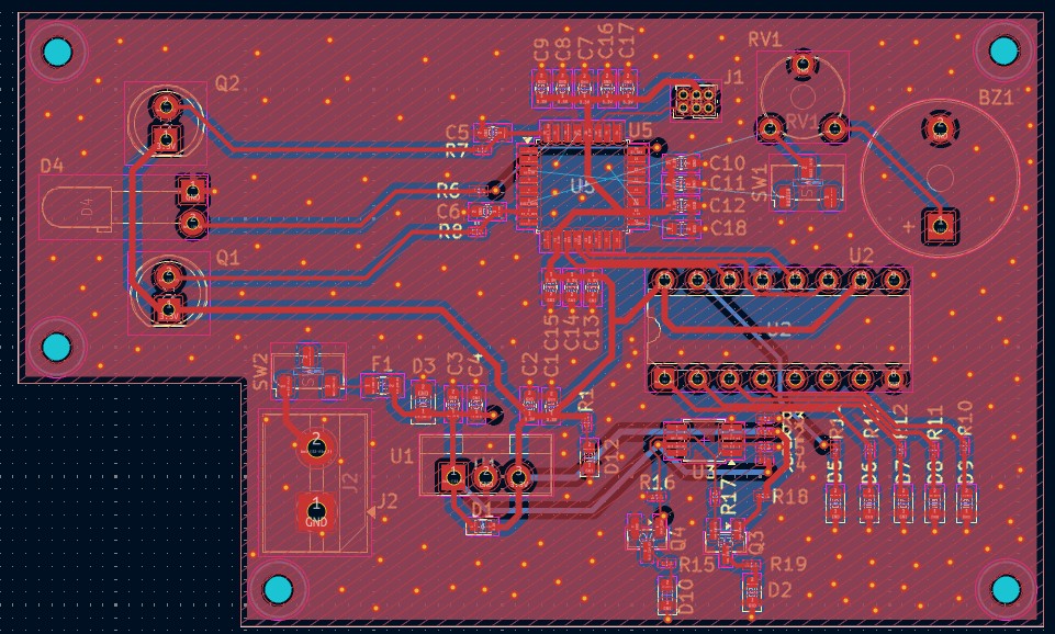
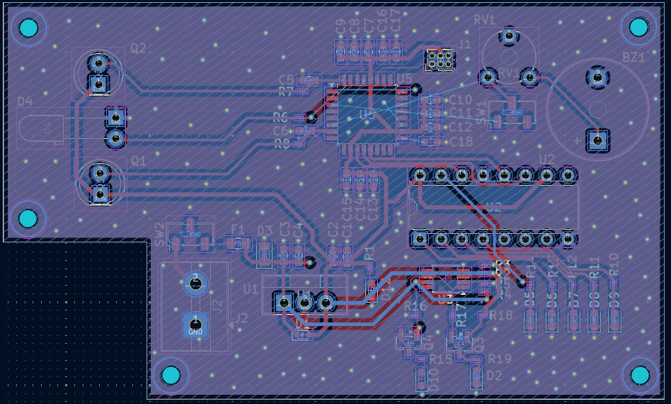
The schematic and PCB were designed in KiCad. I am aware that there is quite a lot of unused space on the board, but this is intentional — the PCB shape and layout were designed to fit a specific enclosure. At this stage, mechanical compatibility and ease of mounting were more important to me than minimizing the board size.
This simple project will be divided into two parts:
Part One – Receiver
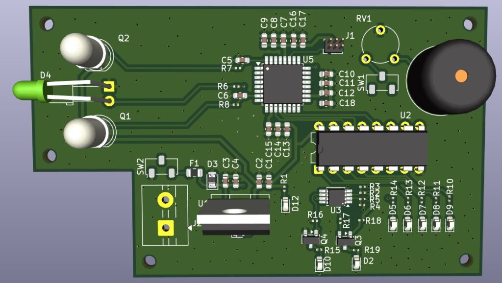
The system is equipped with two phototransistors – one responsible for detecting the main laser beam, and the second acting as an anti-sabotage channel that monitors the signal from an IR diode.
The additional IR diode and second phototransistor are implemented not only to protect the system from an external light source being added, but also to detect other forms of tampering with the receiver. In security systems, such solutions are commonly used to detect attempts to block the sensor, flood it with strong light, inject a constant signal, interfere with the enclosure, or otherwise manipulate the detection circuit. For example, if someone tried to illuminate the main phototransistor with a powerful light source, cover it, replace the original laser beam, or physically interfere with the receiver, the anti-sabotage channel would detect the irregularity and trigger an alarm condition.
Both the receiver circuit, the IR diode, and the laser beam in the transmitter (Part Two) are driven using a PWM signal at a specific, fixed frequency. The receiver therefore does not respond to light intensity alone, but instead analyzes the incoming signal and compares its frequency to a predefined reference value. Only a signal with the correct parameters (frequency and duty cycle) is considered valid.
As a result, adding another laser, flashlight, or any other light source will not be effective. Even if the light reaches the sensor, the system will detect the mismatch in frequency and treat it as a violation. The IR channel works in parallel as an additional control path that confirms proper system operation and detects attempts to bypass the protection mechanism.
Additionally, the receiver will allow adjustment of light sensitivity. When the beam is interrupted, the user will receive a notification on their phone, and a buzzer will also be activated.
The project will be mainly electronics-focused, therefore LED indicators showing the presence of the 9 V power supply will be implemented using comparators. I am aware that this is not strictly necessary, since the circuit will operate at 5 V and be powered by a 9 V battery, but I am doing this primarily for educational purposes. In the past, I really wanted to implement this functionality using comparators, so this project gives me the opportunity to learn and experiment.
Part Two – Transmitter
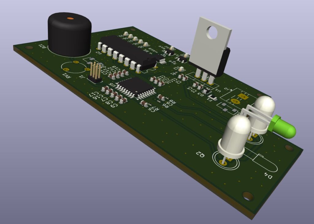
The second part of the project is even simpler, yet it plays a key role in the entire system. It consists of a transmitter primarily based on a laser diode, controlled by an NE555 IC generating a PWM signal. The diode is driven through the NE555 in combination with a MOSFET transistor, allowing precise power regulation. Additionally, the user can adjust the signal modulation and duty cycle using a potentiometer. The circuit also includes a linear voltage regulator, and it can be powered directly from a battery via a convenient screw terminal. Despite its simplicity, this circuit plays an important role in the project, providing a controlled and adjustable laser light source.
KiCad is great for designing circuits, but I personally prefer Fusion 360 or Altium for more advanced projects.
Soon I’ll be starting work on a new project, which I already think will be a bit more challenging. For the first time, I’ll also be sharing a four-layer PCB here, so I’m excited to see how it turns out 🙂