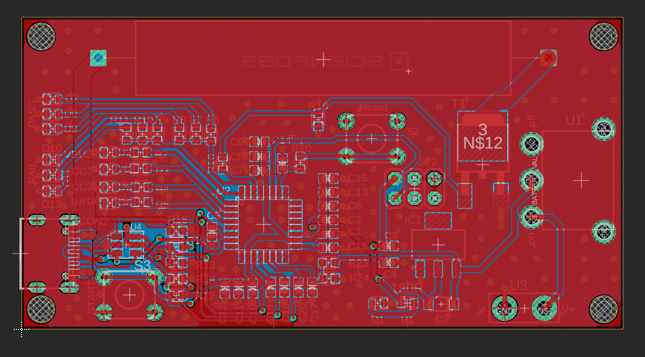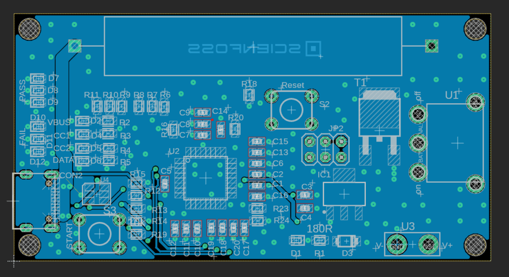
One of the next projects in my portfolio is a USB Tester – a small device designed for anyone frustrated by how a simple USB cable can suffer from significant voltage drops even under a modest load, such as 1A.
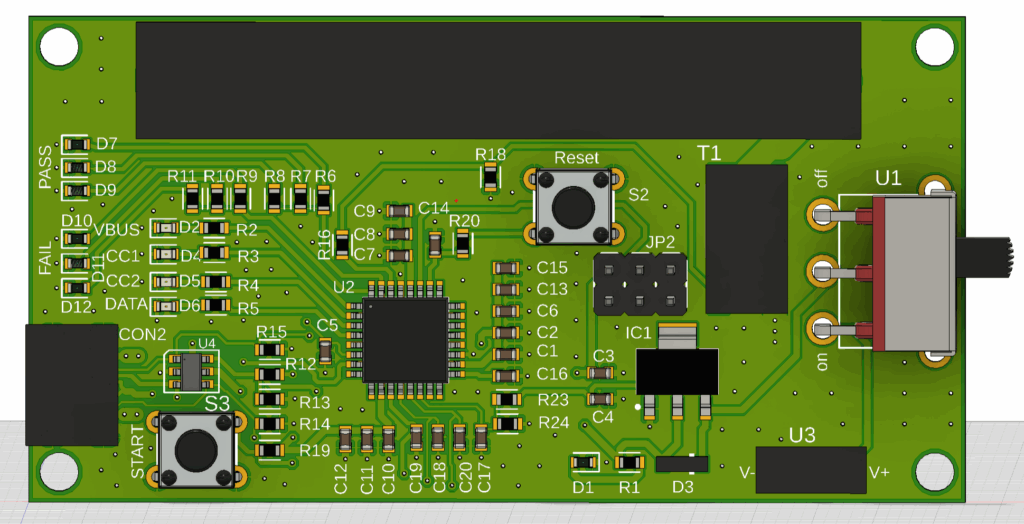
The entire device was designed in Fusion 360. The tester uses its built-in ADC to measure the VBUS, CC1, and CC2 lines, and it also checks the DATA+ and DATA- signals. If all values fall within acceptable ranges, the PASS LEDs light up, and each line has its own dedicated indicator.
If even one measurement goes out of range, the tester switches to FAIL mode, and the LED assigned to the problematic line remains off. This makes it easy for the user to identify exactly where the issue is—whether on the PCB itself or, for example, within the USB cable.
For example: the VBUS measurement is considered valid if, under a 1A load, the voltage does not drop below 4.85 V.
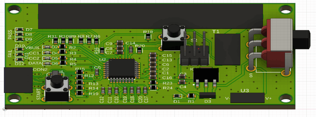
The board also includes components that may appear as simple black squares in the renders—these include a MOSFET used to control the load, the USB-C connector, the battery holder, and also a ceramic power resistor responsible for generating the 1A load. Although not clearly visible in the renderings, it is mounted on the PCB next to these components.
I also programmed the entire device myself to ensure the highest possible accuracy and stability. The project is powered by an AVR32DB32 processor.